After several months of lack of enthusiasm, I seem to have got my mojo back for modelling. It's just a shame that we are in the middle of preparing to move house, so I am restricted in what I can do. The only problem I am having is finding that something I need to use is packed away in one of many boxes. Well, back to the Diamond T and an update on its progress.
I did a little jump on the order of build from the instructions. The next stage of build was meant to be the final bits on the chassis like fuel tanks, steps and the cab. But I decided to start on the cargo body instead, which is typical for me to do. Tried to assemble as par the instructions, but due to the overlength of the body cross braces, I opted to construct both sides and fix them to the body floor. It also helped to hold the braces in place once they were trimmed as there is no location pins on them. Advance warning to anyone planning to build this kit, be prepared for some swearing and cursing during this stage of the build!


After the braces are fitted, the tailgate and rear brace are fitted followed by the benches. These can fitted in either the down or folded positions, I did one of each for this build. Another little warning for you all here. Take care handling the cargo body whilst you are building it. The uprights between the body sides and the upper slats are very delicate, do not put any pressure against them because they will bend or break easily.

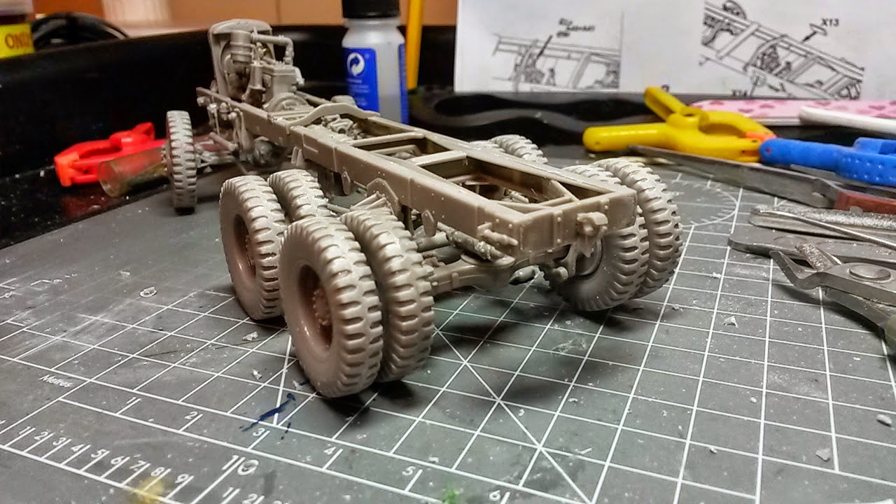
Along the side of the body, you will need to add some lashing hooks which have to be made from some bent wire. Make several extra hooks as you will lose a few to the carpet monster and you may not be happy with the shape of all of the ones you have bent up. In the first photo below, you will see that the rear mudguard is mounted to the extreme rear of the body, as show in the instructions and via the location holes in the floor. This position is incorrect as I discovered from looking at some side view photos of the real truck. The rear mudguards are meant to be the same distance from the rear brace as the front mudguards are from the front brace. They have also missed out supplying the support braces for them to. I also cannot understand why the rear guards are plastic, but the front ones are in etched brass!


As I was removing the rear guards to reposition them, they got slightly damaged along the joint area. So I had to repair these areas by using some Evergreen plastic strips sanding them to shape and size. Further strips of the plastic strip were used to make the guard braces so they would match the front ones. The mudguards are roughly 4mm from the inside faces of the end cross braces, as there is no reference points on the underside of the body to help you. I used the braces of the front guards to get the rough location of them and then transferred the measurement to the rear ones.


That is all for now, I will try and update further as I progress with the build. But I am not sure how much will get done over the next month as we approach the moving date which should be set later this week. So, until next time, happy modelling.