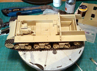
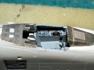
A week has passed and a little more work has been carried out on the Achilles. The progress has been slow due to me finishing painting the Kazon Fighter that I have been building for Kyran. Some photo's of this will be posted soon. Also I have been getting the fuselage of the A-10 primered up ready for painting.
This week, I concentrated on the rear section of the lower hull, around the engine compartment. The kit comes with the fuel tanks, which are hidden by the upper hull. Now this model does have the full interior, except for the engine and compartment sides. So this has left me with having to make a choice whether to have the model where I can remove the upper hull to display the interior or not! But there is no engine in this kit, so I would have to do something about that. So whilst sitting around yesterday at work, out with the Blackberry and a search on the Internet to see if there are any resin GM 6046 engines out there. And yes, there is a kit available that is produced by Tank Workshop, that comes with the choice of engine alone or with the compartment. So the decision has been made, the upper hull will be removable to show the interior detail when required.
Now that I have decided which way I am going with the Achilles, the fuel tanks could be fitted next to the engine compartment walls. I will be ordering the Tank Workshop engine and compartment set over the next few days, hopefully to collect it from the Brampton Show next Sunday. Now there is a few more things to be done on the lower hull before I give it a coat of primer and start painting it.
Now I am starting on the upper hull section, I noticed there was these outlines for the positioning of tools on the rear panel for the upper hull. These do not look that good on a finished model if they can be seen. So prior to removing them, I used a piece of masking film with the locations cut out to use as a guide for locating these tools once the model is painted. Here you can see the raised lines highlighted with pencil to show them up.
In the last post, I mentioned about the Friulmodel track set I had brought for this project. Well here is the box which they came in. I counted the how many links were one of the rubber tracks that came with the kit, 77 on each side. In this link set, there are two different type of links. One set which are the majority of them, have the end connectors between the track plates are at 90 degrees. The rest are with these connectors slightly bent to go around the drive sprocket, idler wheel and the where the tracks curve around the leading and trailing road wheels. But before I start to assemble the links together, first they need to be washed and each link have the track tread glued to each one. Then it is drill out the hole in each link for the wire joiner before assembling the tracks.
I just hope this section of the build drives me around the twist!
Here are the links with the connectors at 90 degrees.
These are the tread plates that need to be glued to each link.


