Now for a big catch up on the Lightning project.
Except for when I was working on the Spitfire for the last month, my main attention has been on the Lightning F.6. But a bit of time was also spent on the McLaren F1 to, that will be covered in a seperate post. Adding all of this extra resin detailing parts, does extend the build time of a project, especially when the manufacturer does not supply instructions on how to adapt the model to accept the aftermarket parts. It is all trial and error!
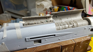
In the last post on this project, I had brought you up to the point of number 2 engine bay cut out and fitted. The next stage was to fit the electronics bays onto the fuselage. The first one was along the spine just in front of number 2 engine. Once the door sections were cut away from the fuselage halves and cleaned up to accept the resin door, the process of fitting the panel with various components on needed its mounting to be worked out.The easiest method was to use some lengths of angled plastistruct as brackets for the panel to sit on. After some sanding, the panel was able to sit in between the fuselage sides low enough down and flush.
Included in the electronics set, was two compartments to fit along the side of the fuselage. First I had to identify the access panels on the fuselage, as the sets instructions did not match up to the fuselage. But using books and photographs online, I had managed to match up the correct access panels on the model and started to cut them out. The resin compartment boxes were then glued in position inside the fuselage and any gaps filled in.
The same problem was found with the flaps, being slightly shorter than the kit flaps. But this was easier to rectify by adding a thin strip of plasticard to the outer end of the flap opening on the wing.
Before assembling the wing halves together, the resin undercarriage bay had to be fitted inside each wing. The only problem here is that the bays are more than 4mm thickand the deepest space between the two wing surfaces inside was 3.5mm. So before removing the moulded parts of the bays from the kit parts, I measured their depths, noted how they curved and which way the curve went. I first cleaned up one wing allowing me to use the other as a reference, then started to file and sand the resin bay to shape. After several test fittings and adjustments, I was happy with how the bay sat inside the wing. I repeated the process for the other wing then once this was finished and I rechecked both bays, they were glued into their positions on the inside of the lower wing surfaces. Below is one of the resin bays before I glued it into the wing.
Now that the bays were fitted, I assembled the two wing halves together and fitted the flaps and ailerons to each wing in the positions I wanted to set them to on the model. The resin undercarriage bays are a vast improvement in detail compared to the moulded kit bays.
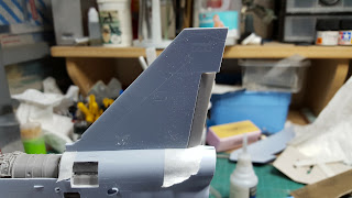
Now that the wings were finished, I moved onto the tail and replacing the rudder on it. This was a straight forward where the moulded rudder was cut away and the edges cleaned up ready to accept the resin rudder. Again I posed the rudder at a slight angle to give it some life, just as if the ground crew was checking the aircraft's control surfaces. I think I might need to get some ground crew figures to go with this model now!
I will finish this post up with the intake section. In the selection of resin part sets, I received a replacement radar unit and front undercarriage bay. This is a two piece set consisting of the bay and radar as one piece, then the shock cone as a separate piece. First the moulded undercarriage bay had to be removed from the intake halves before joining them together. Once this had dried, I could then start filing the opening to accept the replacement part. After some test fits and adjustments, the bay and radar unit fitted correctly inside the intake without the need to use any plasticard to fill gaps. Before I painted the intake and resin part prior to assembly, I drill out some of the waste resin from inside the radar unit and shock cone in case I had to add some weight into them further down the line. After painting, the radar/bay part was glued in position inside the intake.
That is this installment for now and I with continue with more postings of this project very soon. Any comments or questions are appreciated.


